


 Back to Blog
By Lauren Nagel
Distributed electric propulsion (DEP) was invented to try and improve on the modern aircraft: How can we increase an aircraft’s efficiency? Improve its maneuverability? Shorten its take-off and landing distances?
DEP concepts promise to reduce fuel consumption while improving performance, an attractive prospect in a time when we are working tirelessly to make aviation more sustainable.
In this article we cover how DEP works, its pros and cons, and the DEP aircraft to watch. Plus, we offer a solution for testing DEP systems. All included below.
Table of Contents
- What is distributed electric propulsion (DEP)
- How does distributed electric propulsion work
- What are the benefits of distributed electric propulsion
- What are the challenges with distributed electric propulsion
- Notable distributed electric propulsion aircraft
- How to test a distributed electric propulsion system
1. What is Distributed Electric Propulsion (DEP)
Distributed Electric Propulsion (DEP) describes a propulsion system where the thrust generation is distributed across 3 or more electrically-powered propulsors. In many DEP concepts, the electric propulsors (fans or propellers) are distributed in parallel along an aerodynamic surface, such as the wing of an aircraft.
DEP systems may be fully electric, where the electric motors are powered by batteries, or hybrid, where the electric motors are powered by a turbogenerator.
Many notable organizations have DEP concepts under development, including giants like NASA who are actively testing different DEP designs [1].
There is no universally accepted definition of DEP at this time, aside from the requisite presence of multiple electric propulsors.

Figure 1: Lilium Jet in flight (source: New Atlas)
2. How Does Distributed Electric Propulsion Work
Distributed electric propulsion is an evolving concept and no two DEP aircraft are the same. That said, most DEP aircraft tend to fall into one of two main categories: a) fully electric DEP aircraft, and b) hybrid turboelectric DEP aircraft.
1. Fully electric DEP aircraft:
In a fully electric DEP aircraft, a high-density on-board battery acts as the main power source. The batteries drive multiple electric motors that are each individually connected to a propulsor (a fan or propeller). The propulsors produce the thrust required for the aircraft to fly.

Figure 2: Layout of a fully electric DEP aircraft
Examples of fully electric DEP aircraft include the Lilium Jet, NASA’s redesigned X-57 Maxwell, and the Airbus Vahana.2. Hybrid turboelectric DEP aircraft
In a hybrid turboelectric DEP aircraft, the power source is a gas turbine engine connected to a generator that converts mechanical power from the turbine into electrical power. This electrical power travels to the distributed electric motors which in turn rotate the propulsors, generating the required thrust.

Figure 3: Layout of a hybrid turboelectric DEP aircraft
Examples of hybrid turboelectric DEP aircraft include the Aurora XV-24A LightningStrike VTOL Demonstrator, Electra Model EL-2 “Goldfinch”, and the Airbus EcoPulse.
The placement of these components is carefully considered in DEP aircraft as the power sources, propulsors, and aerodynamic surfaces all work together to achieve optimal performance.
In the next sections we discuss these components in more detail, along with the benefits and challenges they offer.
3. Benefits of Distributed Electric Propulsion
There are several potential benefits associated with a distributed electric propulsion system:
Aero-propulsive coupling
The integration of the propulsors into the lift-producing surfaces of the aircraft, such as the leading edge of the wing, leads to an aero-propulsive coupling effect, which can be described as the concerted interaction between aerodynamic and propulsive forces. This takes form in a few different ways:
Boundary layer ingestion (BLI) is an example of this concept, where the propulsors ingest the slower moving air from the boundary layer along the surface of the aircraft. Less energy is required to accelerate this air and it can reduce the total amount of drag produced along that surface, so the fuel efficiency can be increased by up to 8.5% [2].
The E-Thrust concept designed by EADS group (Airbus, Astrium, Cassidian and Eurocopterby) in collaboration with Rolls Royce, was designed to ingest boundary layer air through propulsors seated at the trailing edge of the wing.
The caveat is that the boundary layer air is much more distorted than free-stream air, so stronger propellers or fans are required to process it.

Figure 4: Airbus E-Thrust DEP concept utilizing boundary layer ingestion (source: EADS)
BLI is also a form ofwake filling, a broader term for strategies aimed at reducing the drag caused by an aircraft’s wake, the region of disturbed air behind the aircraft. In DEP aircraft, the strategic placement of the propulsors can contribute to wake filling. For example, propulsors may be placed near the rear of the aircraft to re-energize the airflow as it passes along the fuselage.
Redirection of wind tip vorticesis another aero-propulsive coupling concept that has been studied [3]. The system makes use of propulsor units mounted on the wingtips, where they redirect vortices to enhance propulsion and reduce drag.
Propulsion controlled aircraft (PCA)
A propulsion controlled aircraft (PCA) is an aircraft whose movements, (pitch, roll, and yaw), are controlled by adjustments to the propulsors, rather than traditional control surfaces. Unlike jets and rockets that use thrust vectoring, PCA typically relies only on adjustments to the level of thrust output, rather than changes to the actual shape of the thrust exhaust system.
DEP powered aircraft are prime contenders for propulsion controlled maneuvering, since the thrust of each propulsor can be adjusted independently. This can potentially lead to increased fuel efficiency as the thrust of each propulsor can be fine tuned to meet the power needs of the aircraft.
In most propulsion controlled aircraft, propulsion-powered maneuvering is typically a redundancy that coexists with traditional control surfaces. However, DEP aircraft may offer the first example where this is not the case, allowing for the reduction in size of traditional control surfaces and overall aircraft weight.
An example is the 21% subscale model of a Cirrus SR22T developed by the Department of Aerospace Engineering at the University of Illinois, which is modified for propulsion-based control via 8 ducted fans [3].

Figure 5: The University of Illinois’ distributed electric propulsion-controlled Cirrus SR22T RC aircraft
Bypass ratio
In aircraft propulsion, high bypass ratios are desirable as they offer higher propulsive efficiency and lower noise. In a standard gas turbine engine, the bypass ratio is a measure of the mass of air in the bypass stream relative to the mass of air entering the engine core.
We can also consider the “effective bypass ratio” [1] when discussing certain kinds of DEP systems, which is a measure of the mass of air entering the turbineand propulsors relative to the mass of air entering the turbine engine’s core. This principle is present in NASA’s N3-X turboelectric distributed propulsion (TeDP) aircraft concept [4], where turbogenerators mounted on the wingtips power motors connected to fans mounted on the body of the aircraft (figure 6). The concept has an effective bypass ratio in the range of 29-36:1 [5] with an estimated fuel burn reduction of 70% [6].
For reference, Pratt & Whitney’s PW1000G turbo-geared engine, one of the quietest and most efficient turbofans on the market, has a bypass ratio of 15:1.

Figure 6: NASA’s N3X turboelectric distributed propulsion (TeDP) concept
The practical benefits of the improvements above include:
Reduced operating cost
Two main factors contribute to the potential for reduced operating costs:
- Lower fuel costs: the propulsive and aerodynamic benefits described in the previous paragraphs contribute to increased overall system efficiency, leading to reduced fuel burn and lower emissions.
- Reduced manufacturing and repair costs: Manufacturing several smaller components, such as small electric motors and propellers, may be less costly than manufacturing fewer large units that produce an equal amount of power and thrust. Equally, those components are cheaper to replace when they fail.
Reduced noise
In general, electric propulsion systems produce less noise than equivalent gas-powered systems, as has been demonstrated by multiple studies. One such study conducted by the University of Waterloo noted a 30 dB reduction in noise from training aircraft powered by electric motors compared to their traditional gas powered equivalents [7].
Coupled with the noise reduction offered by the system’s high bypass ratio, DEP powered aircraft should produce significantly less noise than other styles of aircraft with similar performance.
Enhanced take off and landing performance
The aero-propulsive coupling effects described above can produce a blown lift effect, resulting in a relatively higher effective lift coefficient, especially at low speeds. This increased lift at low speeds can significantly reduce the aircraft’s take-off and landing distances, offering the equivalent of short take-off and landing (STOL) performance [8].
As an added bonus, low speed maneuverability is also improved.
Increased redundancy and safety
DEP systems incorporate redundancy on multiple levels, which improves the overall safety of the aircraft. As mentioned, DEP propulsors may be used to maneuver the aircraft, offering a layer of redundancy that can be useful if any of the aircraft’s control surfaces are damaged.
Additionally, the large number of propulsors means that no individual unit plays a singular role in keeping the aircraft in the air. In a system with 8 or 16 propulsors, losing power from one or even a few would not be mission critical.

Figure 7: The Aurora Flight Sciences XV-24 LightningStrike concept has 24 propulsors
4. Challenges with Distributed Electric Propulsion
While offering many potential benefits, distributed electric propulsion also comes with its own set of challenges:
Integration and complexity
The use of electric or hybrid propulsion introduces added complexity and integration challenges.
For example, the heat generated by batteries and electronics stored on board must be managed, and cooling systems add both weight and complexity to the aircraft.
The safe distribution of high-voltage electrical power is also a challenge to be addressed, taking into consideration insulation, electromagnetic interference (EMI), and the combined weight of all components.
Redesign of standard parts
While DEP designs offer certain efficiencies, some design changes are required to achieve them.
For example, in order to benefit from boundary layer ingestion, sturdier fans/ propellers must be designed and manufactured in order to handle the rough boundary layer air.
Similarly, while performance-enhancing effects like blown lift allow for smaller control surfaces, one must also consider what redundancies are required to ensure safety if components of the DEP system fail.
These considerations offer a physical and financial counterbalance to the reduced operating requirements discussed in the previous section.
Scalability and power requirements
As with other electric aircraft concepts, scalability becomes an issue as electrical power supplies still don’t come close to traditional fuels in terms of energy density. Even the most energy dense batteries [9] still only reach a fraction (7%) of the energy density of jet fuel.
Hybrid systems like the TeDP concepts discussed above may help to fill the gap, but those systems present additional and complex challenges (not to mention burning fuel of their own). Similarly, cryogenic systems can provide higher power outputs, but the systems are heavy and less efficient overall on a per kilogram basis.
While DEP powered flight may be possible on a smaller scale, both in terms of aircraft size and trip length, long distance flights in commercial size aircraft are still unfeasible.
5. Notable Distributed Electric Propulsion Aircraft
Below is a list of distributed electric propulsion aircraft concepts that have reached a fairly advanced stage of development, successfully flying a full size aircraft or subscale model.
Electra EL-2 Goldfinch
Electra’s EL-2 Goldfinch is an eSTOL (electric short takeoff and landing) demonstrator that uses distributed electric propulsion and a hybrid-electric propulsion system. The aircraft has eight electric motors and a blown lift architecture to increase wing lift and enable STOL performance. On November 20, 2023, the EL-2 Goldfinch completed its first crewed flight with pilot Cody Allee.

Figure 8: The EL-2 Goldfinch during a test flight on November 20, 2023 (Source)
Lilium Jet
The Lilium Jet features 30 electric motors within the wings and canards flaps that tilt downwards during hover and align flush once in cruise. The system is powered by silicon-anode lithium ion batteries manufactured by CustomCells with a density of 330 Wh/kg. The Lilum Jet has completed several successful uncrewed flight tests to date and the first piloted test is scheduled for late 2024.

Figure 9: The Lilium team with the Lilium Jet (Source)
Aurora XV-24 LightningStrike
The Aurora XV-24 LightningStrike was a hybrid DEP demonstrator built by Aurora Flight Sciences (acquired by Boeing in 2017). The concept employed a Rolls-Royce AE1107C turboshaft engine to power three Honeywell generators, which distributed electric power to 24 ducted fans. A 20% subscale demonstrator flew a test flight at a U.S. military facility on March 29, 2016.

Figure 10: Artist rendering of the Aurora XV-24 LightningStrike (Source)
Airbus Vahana
Aribus’ Vahana aircraft was an all-electric, single-seat, tilt-wing vehicle demonstrator with eight electric motors and a tilt-wing configuration. In November 2019, the Vahana performed its final flight after 138 full-scale test flights. The findings from the Vahana project have been used to develop the newer generations of Airbus urban mobility aircraft, like the CityAirbus NextGen.

Figure 11: The Airbus Vahana eVTOL during a test flight (Source)
CityAirbus NextGen
The CityAirbus NextGen aircraft is a fully electric distributed propulsion vehicle with eight propulsor units. It follows Airbus’ two other demonstrators, Vahana and CityAirbus. The aircraft performed its first ‘power on’ in December 2023 and is scheduled for its maiden flight in 2024.

Figure 12: CityAirbus NextGen in front of the Airbus hangar in Donauworth, Germany
If there is another DEP concept you think we should include on this list, let us know in the comments.
6. How to Test a Distributed Electric Propulsion System
With the complexity of distributed electric propulsion systems, testing is integral to safe development. But how can you test a DEP system?
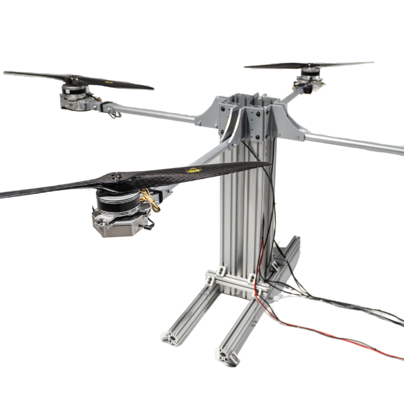
We at Tyto Robotics have developed a platform for testing distributed electric propulsion systems with up to 8 powertrains. It comes with the hardware, software, and electronics needed to measure the performance of 8 motors and propellers simultaneously.
Click here to see our DEP testing platform.

Figure 13: Distributed electric propulsion testing platform
The hardware and electronics use a combination of load cells and sensors to measure your propulsion system’s thrust, torque, RPM, voltage, current, temperature, and power.
These measurements are used to derive motor and ESC efficiency, propeller efficiency, and overall efficiency, for individual powertrains or up to eight powertrains combined.
The testing software allows you to program tests manually, automatically, or with our Python API. We also offer a flight replay feature that allows you to upload flight controller data into the software, using your throttle points as the template for the test.

Figure 14: Distributed electric propulsion testing software GUI
Each powertrain can be mapped and named so data is easy to trace. With live plots displaying incoming data in real-time, you can quickly determine which propulsors are more or less efficient than others.
And if you need to test 8 powertrains simultaneously? Send us a message and we will see how we can help.
References
[1] H. Kim, A. Perry, P. Ansell, "A Review of Distributed Electric Propulsion Concepts for Air Vehicle Technology", 2018 AIAA Propulsion and Energy Forum. https://www1.grc.nasa.gov/wp-content/uploads/2018EATS-Review-of-DEP-Hyun-D.-6.2018-4998.pdf
[2] NASA Glenn Research Center, "Boundary Layer Ingestion Propulsion". Accessed July 10, 2024. https://www1.grc.nasa.gov/aeronautics/bli/
[3] K. Pieper, A. Perry, P. Ansell and T. Bretl, "Design and Development of a Dynamically, Scaled Distributed Electric Propulsion Aircraft Testbed," 2018 AIAA/IEEE Electric Aircraft Technologies Symposium (EATS), Cincinnati, OH, USA, 2018, pp. 1-2.https://ieeexplore.ieee.org/document/8552755
[4] Miranda, L. R., and Brennan, J. E., “Aerodynamic Effects of Wingtip-Mounted Propellers and Turbines,” AIAA Paper 86-1802, June 1986. https://arc.aiaa.org/doi/10.2514/6.1986-1802
[5] NASA Glenn Research Center, "N3X". Accessed July 10, 2024. https://www1.grc.nasa.gov/aeronautics/eap/airplane-concepts/n3x/
[6] "NASA N3-X with Turboelectric Distributed Propulsion", Fundamental Aeronautics Program Fixed Wing Project. James L. Felder. NASA Glenn Research Center Cleveland, Ohio. Accessed July 10, 2024. https://ntrs.nasa.gov/api/citations/20150002081/downloads/20150002081.pdf
[7] Noisy neighbours: Do electric aircraft reduce airport noise pollution? by Paul Parker and Gabriel Song. January 2024.https://uwaterloo.ca/sustainable-aeronautics/blog/noisy-neighbours-do-electric-aircraft-reduce-airport-noise
[8] Qin, Jiachen and Zhou, Zhou and Yang, Guowei and Shao, Zhuang and Zong, Jia, "Aero-Propulsive Coupling Modeling and Dynamic Stability Analysis of Distributed Electric Propulsion Tandem-Wing Uav with Rapid Ascent Capability", April 2024. https://ssrn.com/abstract=4783514
[9] Quan Li et al 2023 Chinese Phys. Lett. 40 048201https://iopscience.iop.org/article/10.1088/0256-307X/40/4/048201


Leave a comment