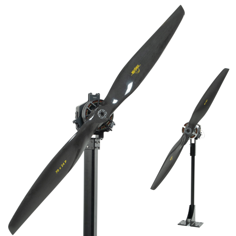
“The results show that for unequal combinations, the user should place the smaller propeller upstream for greater efficiency, but for maximum thrust capacity, two equal propellers are preferred”
In their recent study,Investigation of the Performance Characteristics of Unequal Co-Axial Rotors, Max Miles and Dr. Stephen D. Prior investigate how different propeller sizes and separation distances affect the thrust, efficiency, and power consumption of UAV propulsion systems.
Previous studies indicated that positioning a smaller propeller upstream of a larger propeller could improve performance, with an optimal separation ratio (z/D) in the range of 0.1 to 0.4. Dr. Prior’s team set out to further validate these findings and expand our understanding of co-axial rotor dynamics.
Test Setup
The experiments were conducted using the Flight Stand 15 Pro, a thrust stand well-known to the team. Dr. Prior remarked, “We have used a range of TYTO Thrust Stands (1585, 1780, and FS15) over the last decade to improve our understanding and measurement of scale propellers.” The team also developed a custom MATLAB script to optimize propeller designs and test a range of 3D-printed propellers tailored for specific operational envelopes.
Figure 1:Flight Stand 15 Pro thrust stands in a face-to-face coaxial configuration
Each propeller was powered by a U8 Kv100 electric motor from T-Motor, with performance corrected to Kv80 following initial validation. Motors were driven by a T-Motor Alpha 60A 6S ESC and powered by fully charged 25C 6S (22.2 V) Li-Po batteries.
The study tested combinations of 26″ and 29″ T-Motor carbon fiber propellers across five z/D ratios: 0.05, 0.1, 0.2, 0.3, and 0.35. The z/D ratio being the ratio of the distance between the blades, z, and the blade diameter, D.
Both propellers were run at equivalent throttles. Starting at 20% throttle, the system was given time to settle before increasing the throttle by five per cent, up to 90% throttle. The thrust stand software recorded thrust, current, torque, RPM, electrical input power, and mechanical output power.
Propellers were first tested in isolation to establish a baseline for comparison against the experimental co-axial configurations. This baseline is referred to as the “ideal co-axial pair”: two isolated propellers acting independently of each other with no interference between them.
Below we’ve summarized some of their key findings.
Results
Separation Distance (z/D Ratio) Optimization
The optimal separation distance, in terms of minimal thrust loss, varied slightly between configurations. The results followed the characteristic “bucket” shape, where performance is poor at a small separation, improves as the separation increases, then eventually declines again, as seen in figure 2.
The ideal z/D ratio was 0.2 for the unequal pair with the smaller propeller upstream, while for other configurations, the optimal separation was between 0.1 and 0.2.
Figure 2: Thrust losses for equal and unequal co-axial powertrains, when compared to an ideal co-axial pair
Thrust Loss
Figure 3 depicts the % thrust loss of each coaxial propulsion system compared to the ideal co-axial pair. For unequal propeller combinations, positioning the smaller propeller upstream resulted in the lowest losses of thrust.
A 26″ upstream propeller paired with a 29″ downstream propeller showed the minimum thrust loss of 17.3%, whereas the reverse configuration resulted in a 23.8% loss.
Figure 3: Thrust loss for different co-axial systems compared to an ideal pair
Total Thrust
When comparing the total thrust production of each configuration, equal propeller pairs produced the highest net thrust. The pair of 29″ propellers achieved 34.9 N of thrust at maximum throttle, which was 12% higher than the best-performing unequal combination.
Within the unequal pairs, the configuration with the smaller 26” propeller upstream of the larger 29” propeller produced 2.2 N more thrust at maximum throttle than the reverse configuration, a 7.5% increase.
Figure 4: Total thrust produced by equal and unequal co-axial propeller combinations
To try and eliminate propeller size as an influencing factor, they normalised the total thrust to the disk area of the co-axial propeller, referred to as disk loading.
With this normalization in place, they observed that the larger equal pair of 29” propellers achieved the highest disk loading and greatest total thrust production at any rotation speed from 400 - 1700 RPM.
Figure 5: Co-axial disk loading by RPM
Power Consumption and Efficiency
The downstream propeller, positioned in the wake of the upstream propeller, required additional power to produce the same thrust as an isolated propeller. Both unequal pairs saw a smaller increase in power compared to the equal pairs. The small-leading unequal pair showed a power increase of 22.7%, whereas equal pairs exhibited a power increase of 27%.
Figure 6: Percentage power increase for co-axial systems compared to an ideal pair
Conclusion
This study provided an in-depth look at the relationship between co-axial rotor configuration and performance. It validated several existing findings and contributed valuable insights into how thrust, power, and efficiency are impacted by propeller position, separation distance, and relative size.


 Back to Blog


Leave a comment