
 Back to Blog
A thrust stand is essential for testing your propulsion system’s thrust, torque, RPM, and efficiency. Integrating sensors into your tests adds another layer of optimization that can take your performance to the next level.
In the unmanned industry, it is well documented that collecting data from external sensors can be challenging.[1] To address these issues, we’ve developed a new software feature called “Input Transformations.” This feature allows you to connect external analog sensors to all our Flight Stand products, so you can seamlessly integrate sensor data with your propulsion readings.
In this article, we demonstrate how to connect analog sensors to your Flight Stand, provide use cases that highlight the benefits of additional sensors, and we touch on some of the challenges you may face during tests.
Table of contents
- How to connect external sensors to your Flight Stand
- Which external sensors to use to test your propulsion system
- Challenges of testing with external sensors
How to connect external sensors to your Flight Stand
In this section we explain how to connect external sensors to your Flight Stand. We will demonstrate using a sound sensor to show how you can use propeller noise measurement to optimize for a quieter flight experience.
If you prefer a video demonstration, watch how we connect the sensor to ourFlight Stand 15:
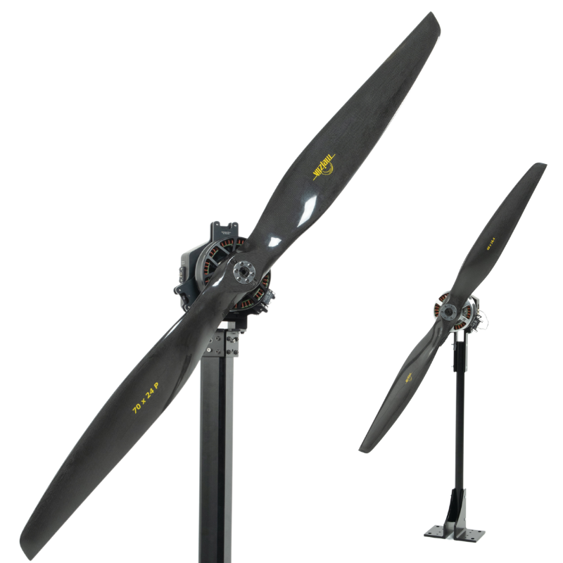
Specifically, we will measure the decibel levels generated by a propulsion system (Xoar 26-inch propeller + AXI 8110 motor) by connecting aSEN0232sound level meter to our Flight Stand 15 Pro thrust stand. This probe operates with a 5V voltage input and measures sound levels ranging from 30dBA to 130dBA.
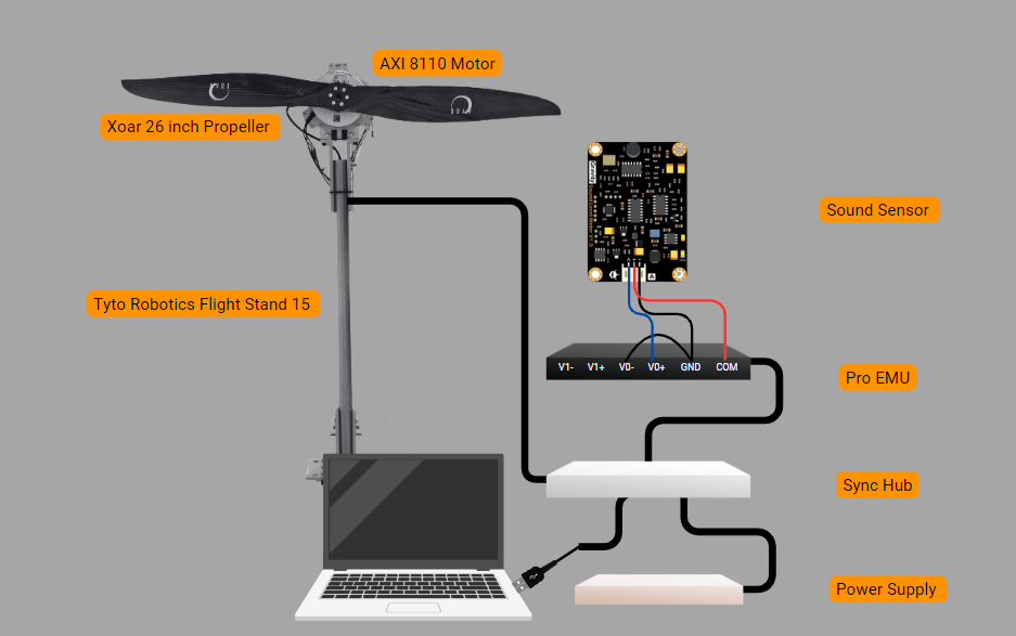
Figure 1: The Flight Stand Testing Set Up
You can test various sensor placements and motor/propeller combinations to determine which configuration minimizes noise.
Steps to connect the sensor:
In the Flight Stand software:
- Verify that the Flight Stand hardware is connected via USB.
- Navigate to the Input Transformations tab.
- Click “Add new transformation”.
- Under “Name”, you can type an alias for the sensor (e.g., “Sound Sensor”).
- Select your unit type or select “Custom units” and input "dB" for decibels.
- Assign the voltage general analog input to variable “a”.
- In the “Formula” field, type the conversion formula provided in the sensor’s datasheet, in our case: a * 50: Decibel Value (dBA) = Output Voltage (V) × 50
-
Enter system limits based on the datasheet specifications to trigger an automatic motor cut-off if the sound level exceeds the defined range.
-
Click “Save”

Results
After analysis, the graphic results below show that at a maximum throttle of 1500μs and 1099.45 RPM, this propulsion system generates 76.18 dB of noise. We would then decide whether this is an acceptable level of noise, and if not, we could proceed with testing other powertrain combinations to achieve a lower noise level.


This example of connecting analog sensors to your Flight Stand highlights the potential of external sensors to significantly enhance propulsion system development.
Why use external sensors to test propulsion systems
Sensor data can be key in making informed decisions related to UAV development. The additional data that sensors provide can lead to the creation of more efficient, reliable, and safer UAVs.
Here’s a few reasons to add external sensors to your test setup:
To Gather Additional Performance Data
Efficiency is one of the most important metrics for evaluating UAV performance. Here’s a few off-the-shelf sensors that can help you achieve higher efficiency:
- Cylinder Pressure Sensors: Monitoring cylinder pressure variations enables you to fine tune your fuel-air mixture, enhancing the performance of propulsion systems that use internal combustion engines.[3]
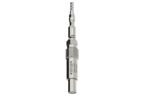
Figure 4: Kistler Type 6125C piezoelectric pressure sensor
- Thermal Sensors: Tracking the temperature of critical components to prevent overheating, mitigating the risk of heat-related environmental hazards and ensuring that the propulsion system does not adversely affect its surroundings.[5] Note that the Tyto Robotics temperature sensor plugs in directly to the force measurement unit.

Figure 5: Tyto Robotics PT-100 Temperature Sensor
To Improve Reliability
Testing performance against environmental factors using external sensors helps predict discrepancies when the UAV operates in real-world conditions. Examples of such sensors include:
- Humidity Sensors: Testing with various humidity levels can help you determine how to maintain consistent thrust output under diverse environmental conditions.[4]

Figure 6: B+B Sensors HYTE-ANA-1735 Calibrated Humidity Module
- Air Speed Sensors: Measuring airflow around the propulsion system can help you identify areas of laminar and disturbed flow, leading to design adjustments to reduce drag and improve maneuverability.

To Measure Noise
You can also use external sensors to decrease operational risk, especially in specialized UAV flight applications such as agriculture, military, and logistics. For example:
- Sound Sensors: Monitoring noise levels to detect excessive noise pollution and potential mechanical issues, helping to ensure that the propulsion system operates within environmentally acceptable noise limits. Read more about how noise is linked to propeller performance.

Challenges of testing with external sensors
Testing propulsion systems with external sensors presents several challenges that must be addressed to ensure accurate and reliable data collection.
- Interference and Noise: Propulsion systems generate electromagnetic interference (EMI) and mechanical vibrations that can affect the accuracy of external sensors.[6] Stabilizing techniques must be considered to minimize these effects and ensure reliable sensor readings.
- Data Integration: Integrating data from multiple sensors can be complex.[6] Ensuring that data collection is correctly interpreted requires advanced software algorithms and data processing capabilities.
- Durability: External sensors used in propulsion testing must withstand harsh operating conditions, including high temperatures, vibrations, and potential impacts.[1]
How our Flight Stands solve these problems:
- Solid-State system: Our monoblock load cell reduces vibrations that jeopardize the accuracy of data measurements.
- Seamless data integration: The Flight Stand software precisely syncs data measurement at a sampling rate up to 1,000 Hz, allowing for seamless data integration.
- Custom formulas: The software supports custom formulas to match any algorithm being tested, so you can use whatever sensors meet your operating requirements.
If you have any further questions don’t hesitate to leave us a comment below.
References
[1] Balestrieri, E., Daponte, P., De Vito, L., & Lamonaca, F. (2021). Sensors and Measurements for Unmanned Systems: An Overview. Sensors (Basel, Switzerland), 21(4), 1518.https://doi.org/10.3390/s21041518
[2] Ghazali, M. H. M., & Rahiman, W. (2022). An investigation of the reliability of different types of sensors in the real-time vibration-based anomaly inspection in drones. Sensors, 22(16), 6015.https://doi.org/10.3390/s22166015
[3] Ratiu, S., Popa, G. N., & Alexa, V. (2010). Monitoring of the pressure inside the cylinder for an internal-combustion engine. ResearchGate.https://www.researchgate.net/publication/228874236_Monitoring_of_the_pressure_inside_the_cylinder_for_an_internal-combustion_engine
[4] Mikhelashvili, L., Barash, Y., Kiviniski, I., Gortinsky, L., & Neudachin, K. (2024). Formation and optical properties of LSPR-active nanowires: Role of substrate and environmental conditions. Journal of Physics: Condensed Matter, 36(10), 105703.https://doi.org/10.1088/1361-6463/ad60d8
[5] Tyto Robotics. (n.d.). How to check electric motor temperature sensor. Tyto Robotics. Retrieved August 1, 2024, fromhttps://www.tytorobotics.com/blogs/general-knowledge/how-to-check-electric-motor-temperature-sensor
[6] Dewesoft. (n.d.). What is sensor fusion? Dewesoft Blog. Retrieved August 2, 2024, fromhttps://dewesoft.com/blog/what-is-sensor-fusion


Leave a comment